C = COVER STYLE |
G = GASKET STYLE |
– 1 =ALT. TAP & CLEAR |
– 2 =ALL TAPPED |
– 3 = ALL CLEAR |
|
3.5 – 40.0 GHz
1.15 Typical Max VSWR (VSWR varies with design)
Forced Air Cooling
Manufactured Designs vary with Power specifications
Numerous Flange Configurations available
Aluminum (6061) Waveguide Available
Contact Sales Staff for Designs options
Advanced Microwave Components is proud to offer quality waveguide terminations in a flash! Our waveguide sections are manufactured to our customer’s specifications.
All AMC components are produced with the highest quality available. We insure our quality through a ISO9001 / AS9100 certified quality system.
All parts are painted high heat flat black and flanges are polished, unplated and iridited.
WR SIZE | FREQ: GHZ | Ref. DIM. ” L “ | POWER (CW) |
180 | 18.0 – 40.0 | 5.0 | 25 |
110 | 11.0 – 26.5 | 6.0 | 75 |
750 | 7.50 – 18.0 | 8.0 | 200 |
650 | 6.5 – 18.0 | 8.0 | 200 |
580 | 5.80 – 16.0 | 8.75 | 250 |
475 | 4.75 – 11.0 | 10.0 | 300 |
350 | 3.50 – 8.20 | 12.0 | 400 |
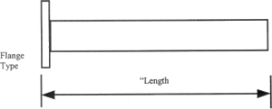
MODEL NO: | WAVEGUIDE SIZE | FLANGE TYPE | POWER CW | MATERIAL A= ALUMINUM
|
AMC-DRMPT | 580 | -C1- | 250 | A |
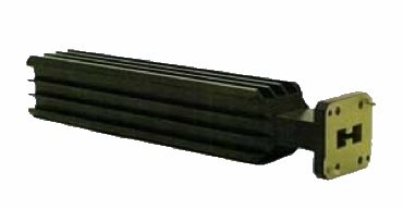
The above referenced part number describes the following item: WRD580 Medium Power Termination, a cover flange with alternate tap & clear holes, made of aluminum.
Note: All AMC models include an iridite/corrosion protection treatment and are painted high-temperature flat black. Flanges are unplated, polished and iridited. Other finishes